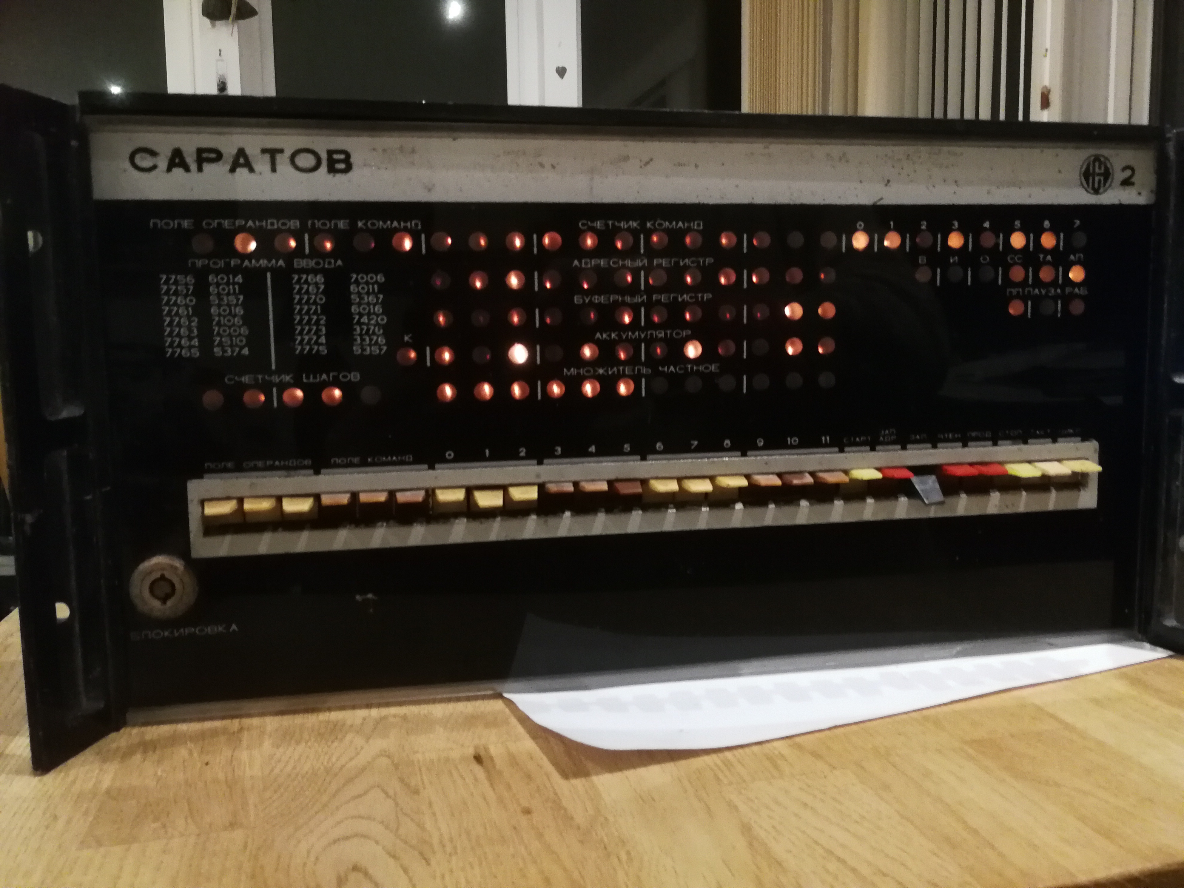
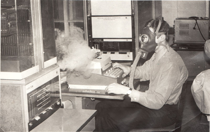
I am the owner of a ?Russian? Capatob (Saratov) front panel.
Apparently the saratov series of computers were pdp-8 clones, copied from a
pdp-8 recovered from a sunken US submarine. I dont know how true that is.
I plan to re-activate it using Jörg Hoppes Blinkenboard kit.
The first stage was to try to find documentation for the Saratov
2 board.
That failed badly - can anyone help?
So, the current stage is to trace the wires and produce a circuit
diagram....
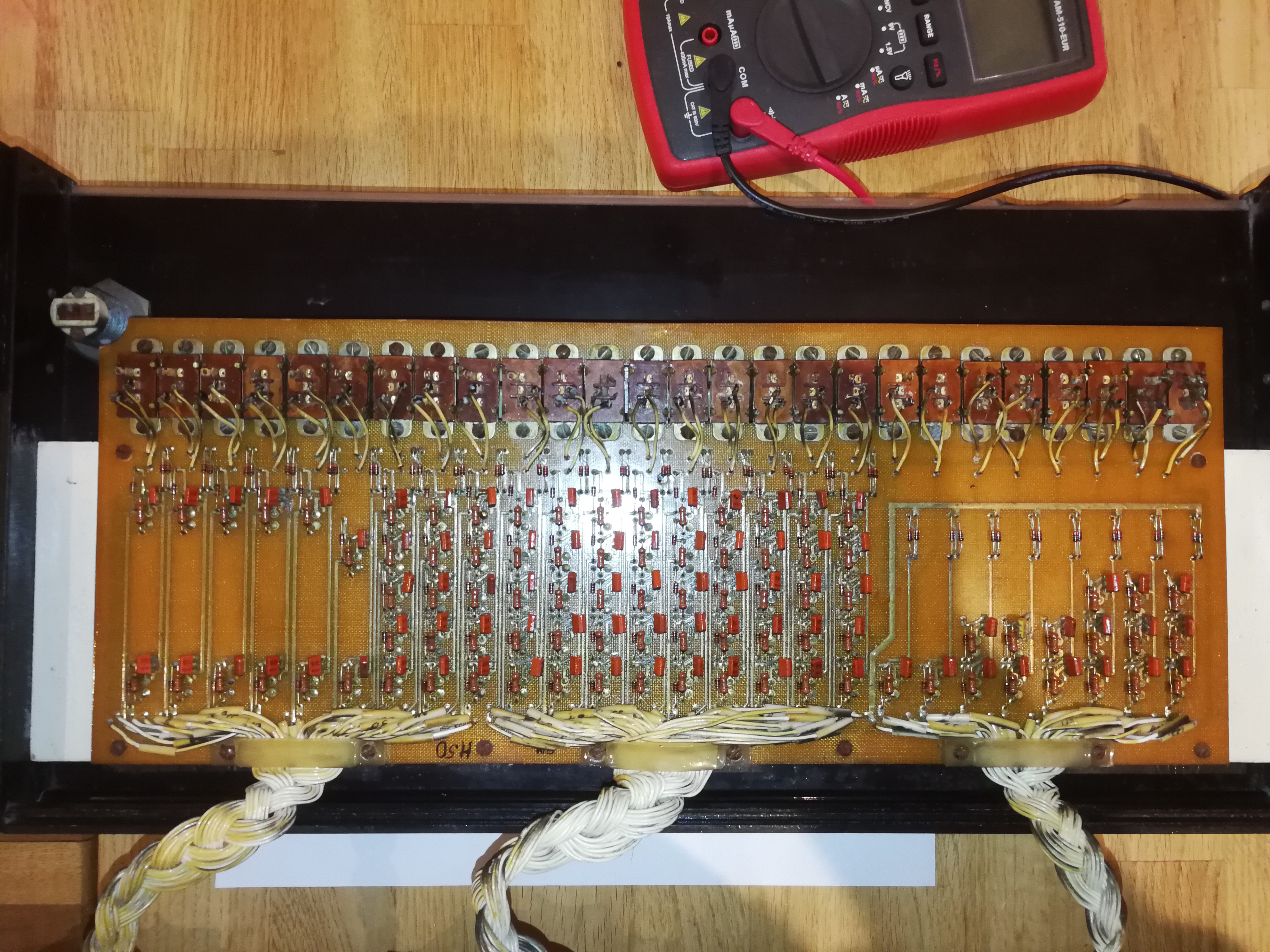
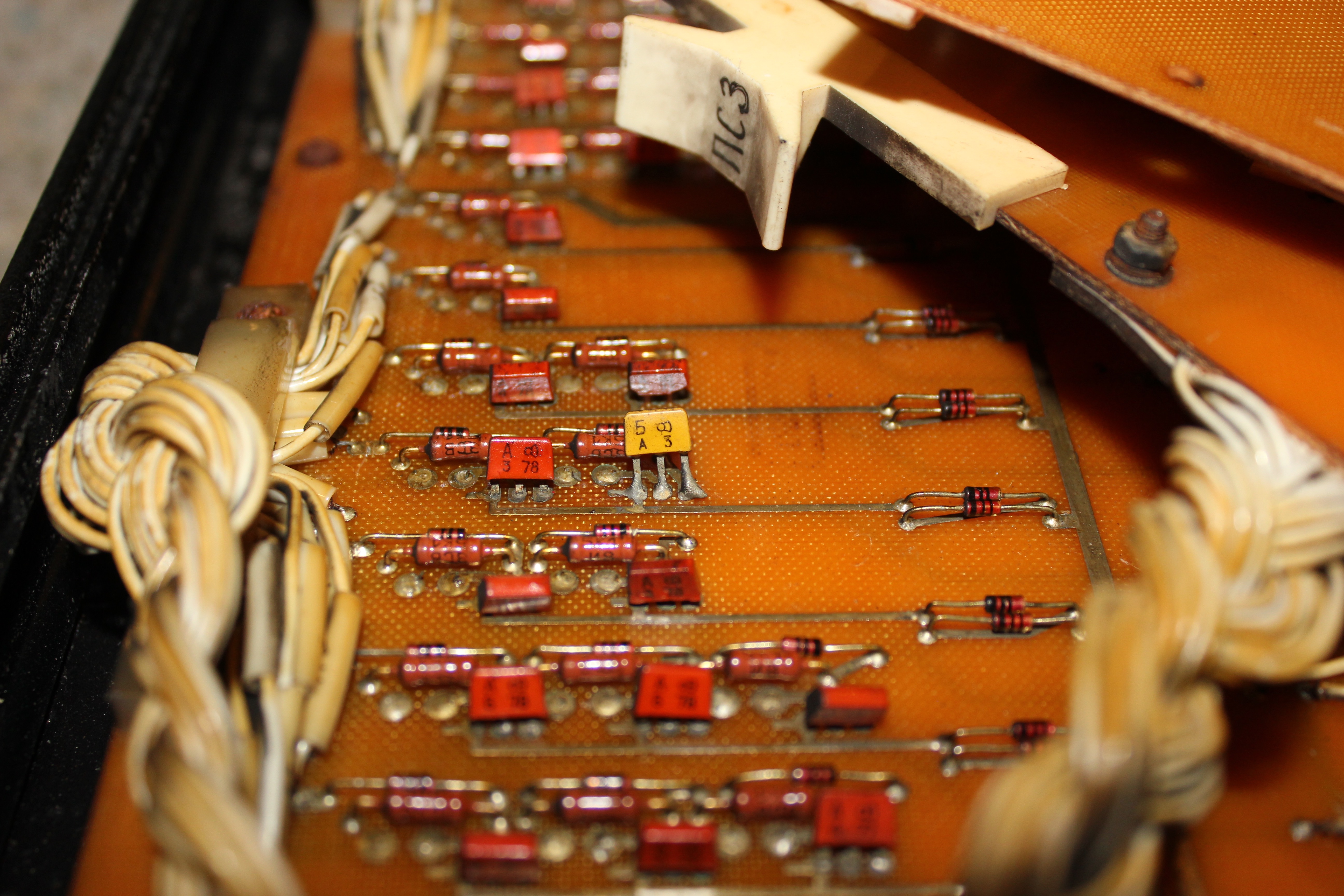
Here are some pictures of the board
front:
 The slow-speed RIM loader?
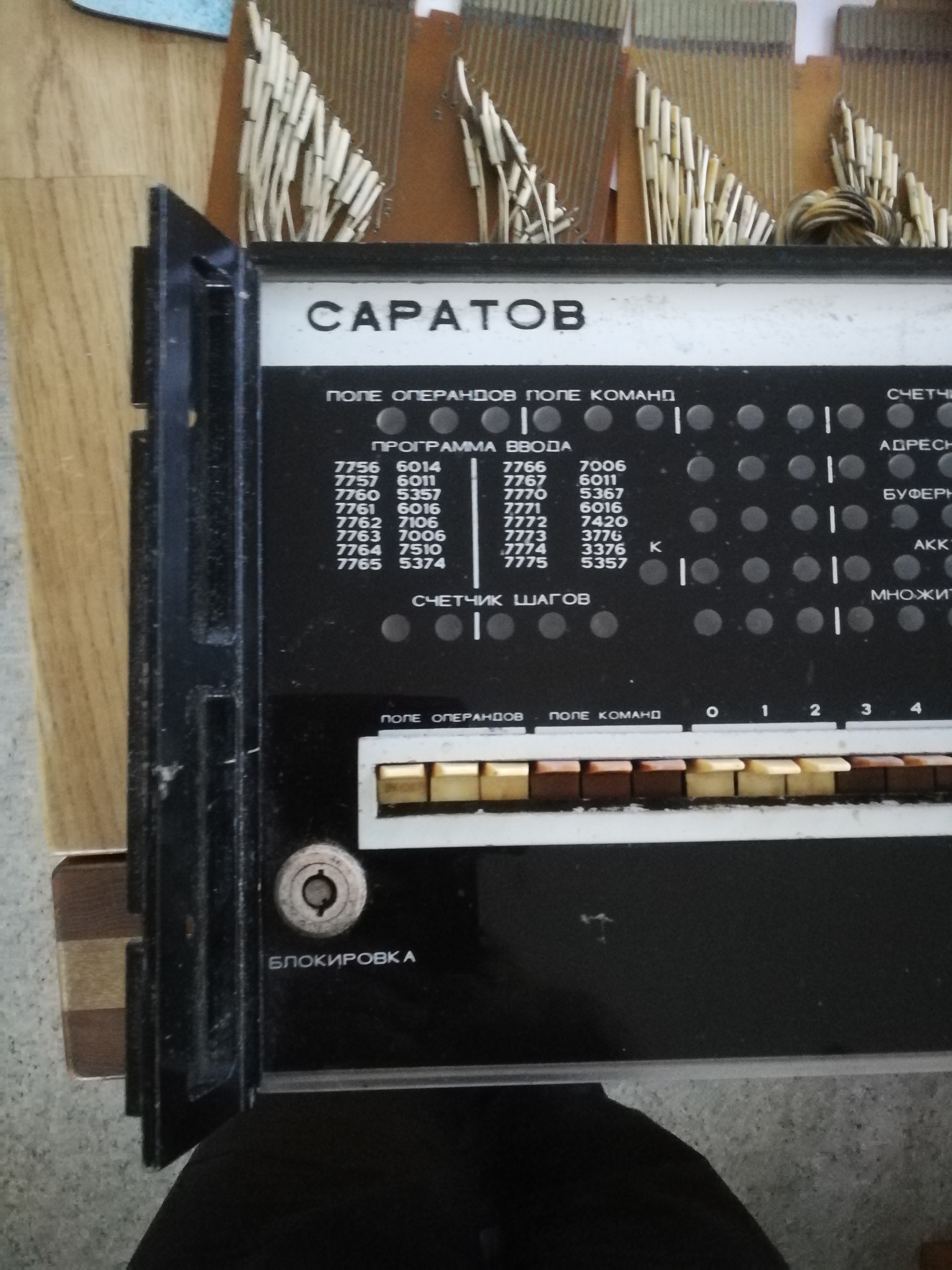
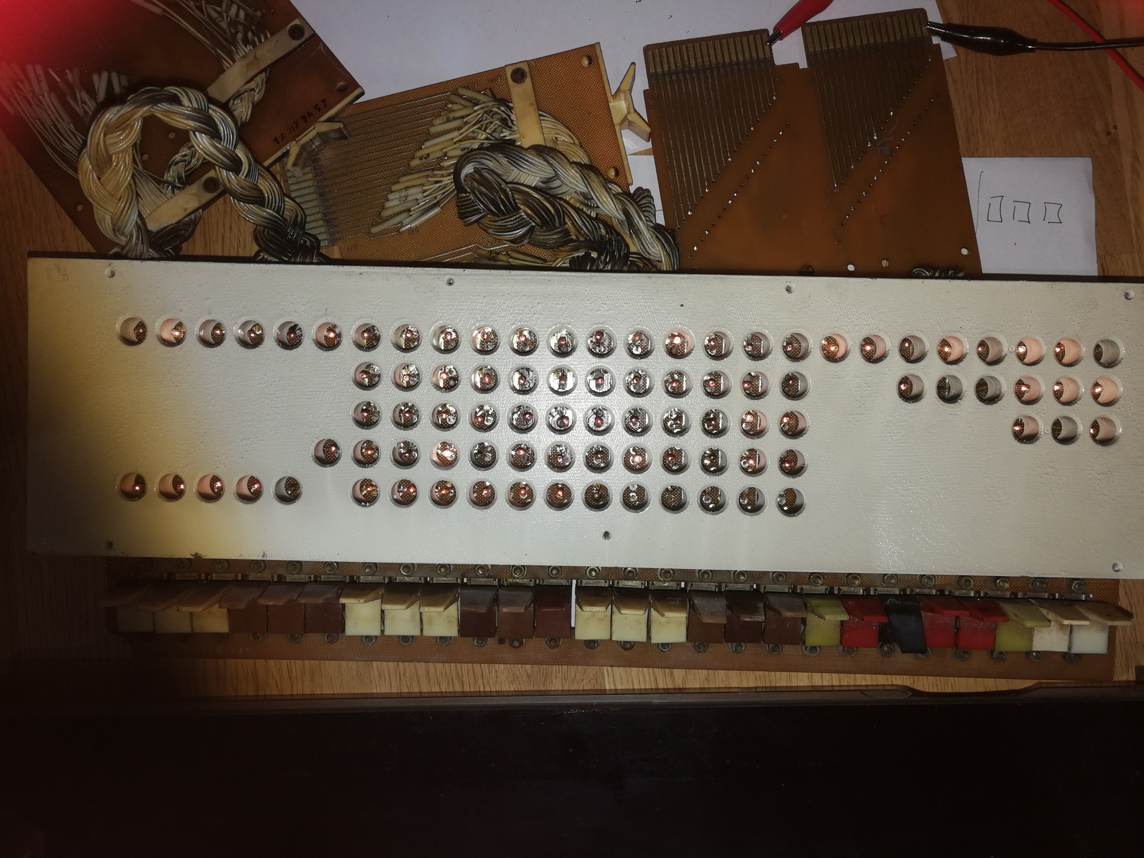
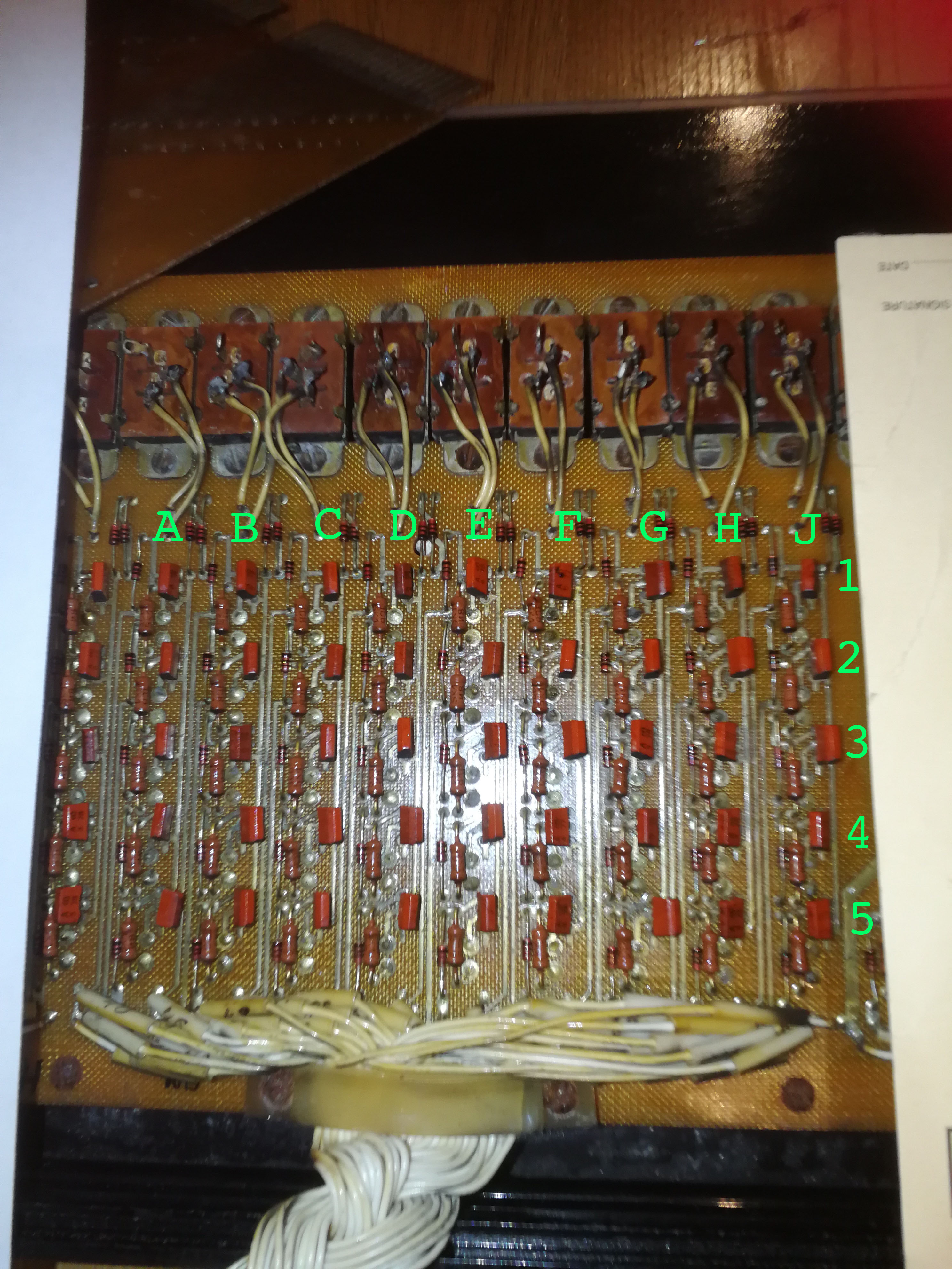
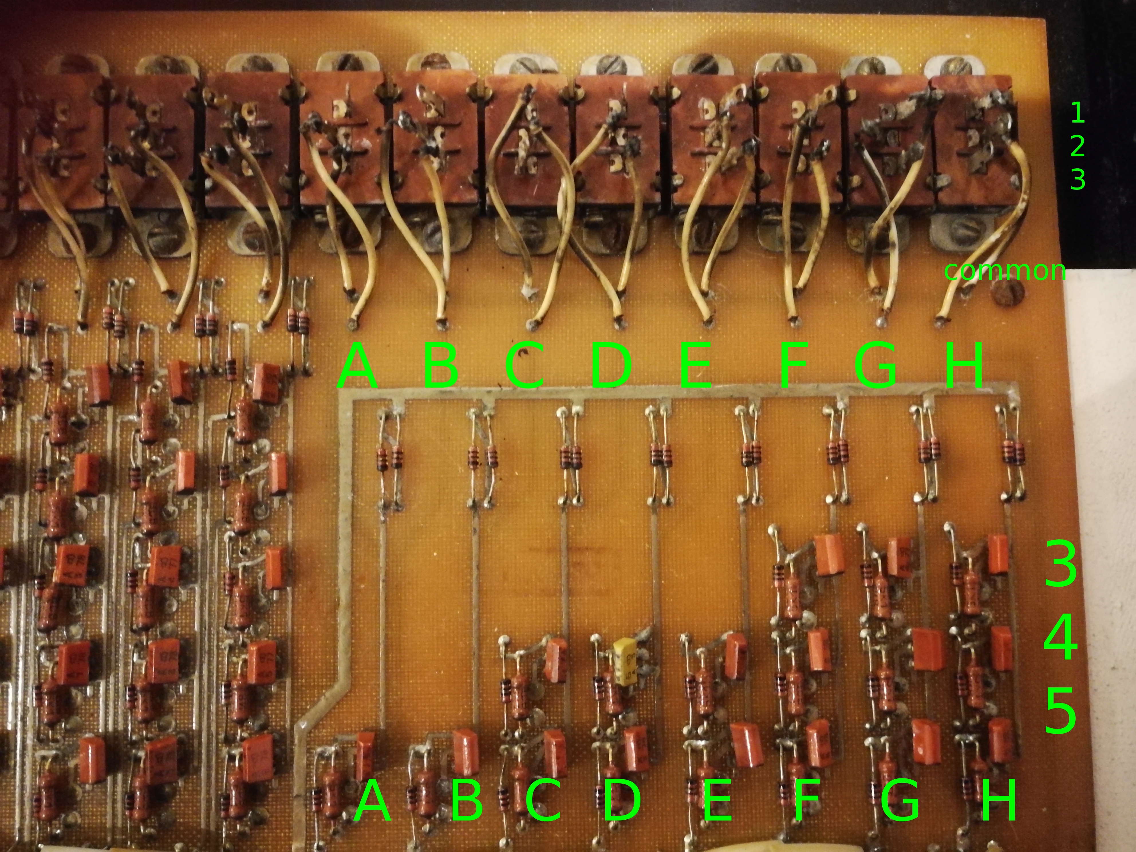
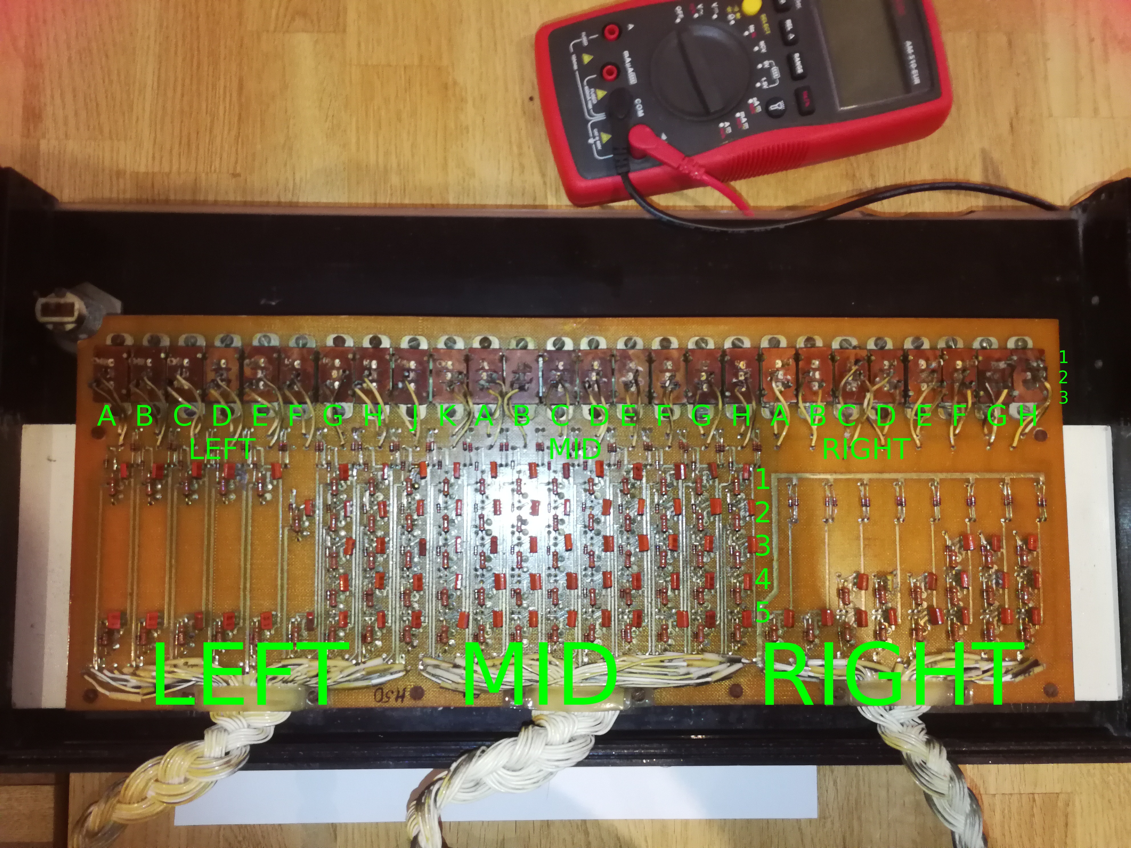
back:
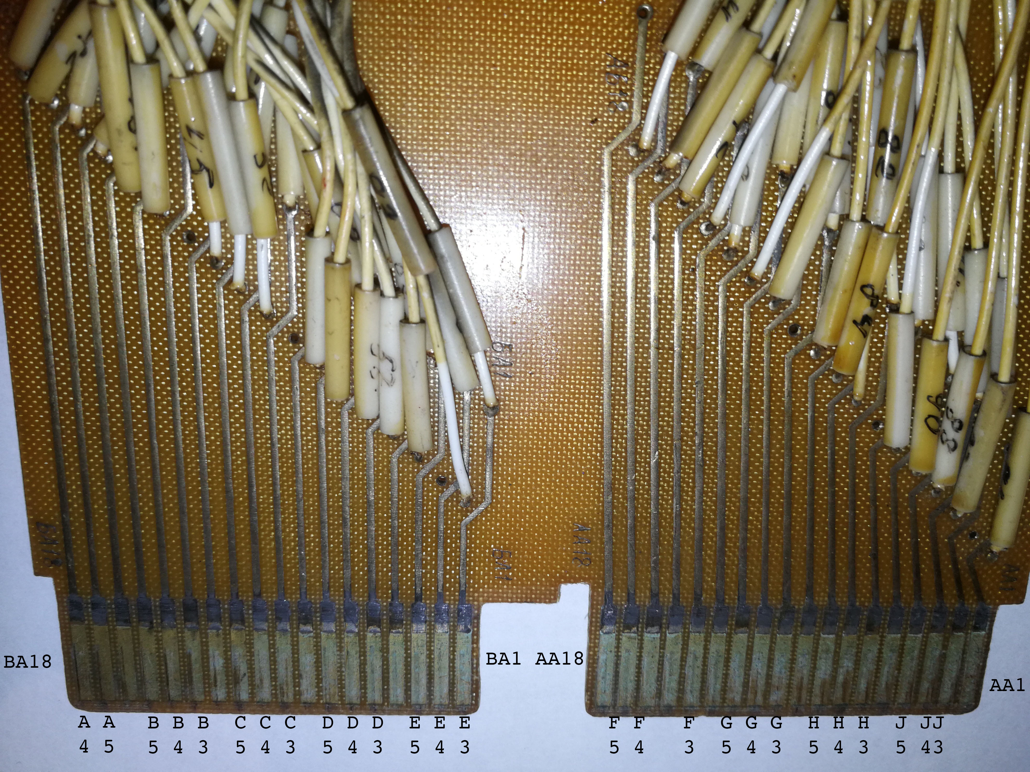
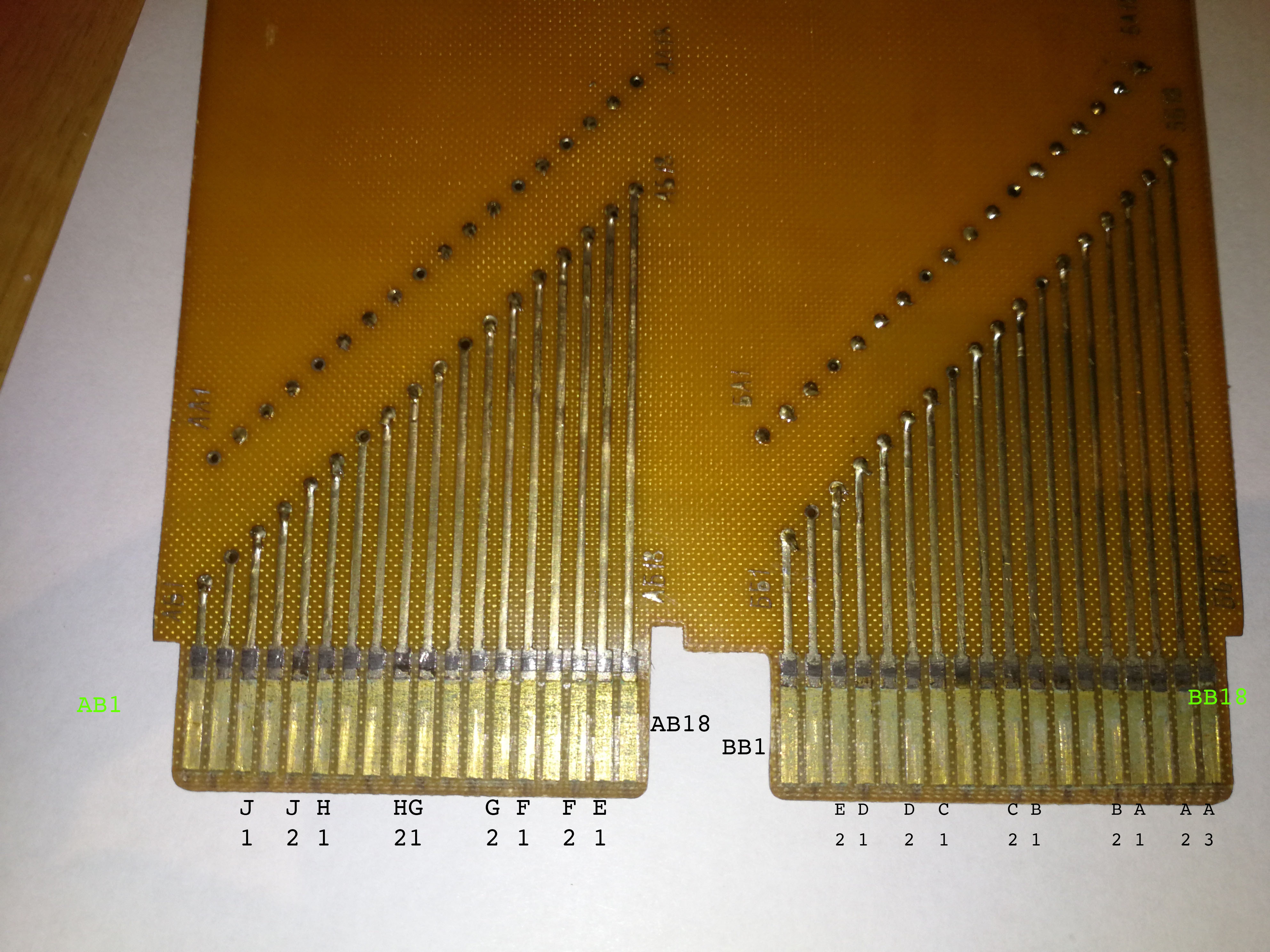
and here is the pinouts for the "middle" section of the
board. This is the block that the PC2 connector attaches to.
The left (PC1) and right (PC3) connector documentation is in process of preparation.
mid-connector, and the names I have put on the lights as they appear in the column below
|
| |||||||||||||||||||||||||||||||||||||||||||||||||||||||||||||||||||||||||||||||||||||||||||||||||||||||||||||||||||||||||||||||||||||||||||||||||||||||||||||||||||||||||||||||||||||||||||||||||||||||||||||||||||||||||||||||||||||||||||||||||||||||||||||||||
"Middle" connector - PC2 - signal names later
AA1
AA2	J3
AA3	J4
AA4	J5
AA5
AA6	H3
AA7	H4
AA8 	H5
AA9
AA10	G3
AA11	G4
AA12	G5
AA13
AA14	F3
AA15
AA16	F4
AA17	F5
AA18

BA1	E3
BA2	E4
BA3	E5
BA4
BA5	D3
BA6	D4
BA7	D5
BA8
BA9	C3
BA10	C4
BA11	C5
BA12
BA13	B3
BA14	B4
BA15	B5
BA16
BA17	A5
BA18	A4

AB1
AB2
AB3	J1
AB4
AB5	J2
AB6	H1
AB7
AB8
AB9	H2
AB10	G1
AB11
AB12
AB13	G2
AB14	F1
AB15
AB16	F2
AB17	E1
AB18

BB1
BB2
BB3	E2
BB4	D1
BB5
BB6	D2
BB7	C1
BB8
BB9
BB10	C2
BB11	B1
BB12
BB13
BB14	B2
BB15	A1
BB16
BB17	A2
BB18	A3

"Right" connector - PC3 - signal names later
AA1
AA2
AA3
AA4
AA5
AA6	H3
AA7	H4
AA8 	H5
AA9
AA10	G3
AA11	G4
AA12	G5
AA13
AA14	F3
AA15
AA16	F4
AA17	F5
AA18

BA1
BA2	E4
BA3	E5
BA4
BA5
BA6	D4
BA7	D5
BA8
BA9
BA10
BA11	C5
BA12
BA13
BA14
BA15	B5
BA16
BA17	A5
BA18

AB1     common ground for lights
AB2
AB3
AB4
AB5
AB6
AB7
AB8     SW-H2
AB9
AB10
AB11    SW-common (ground?)
AB12    SW-G2
AB13
AB14
AB15    SW-F2
AB16
AB17
AB18    SW-E2

BB1	to all 5K1 resistors so +5
BB2
BB3
BB4
BB5     SW-D2
BB6
BB7
BB8
BB9     SW-C2
BB10
BB11
BB12
BB13	SW-B2
BB14
BB15
BB16    SW-A2
BB17
BB18


Right section PC1

   ab11 swr4 top
   ab18 swr4 middle

   ab11 swr5 top
   bb5 swr5 middle

   ab11 swr6 bottom
   bb9 swr6 middle

   ab11 swr7 top
   bb13 sw7 middle

   ab11 swr8 top
   bb16 sw8 middle

The bulbs all appear to be wired up as below:


----------------------+ AB1
                      !
                      V D1 Diode
                     ---
                      !
                      V D2 Diode
                     ---
   D3                 !    D3 no idea of direction yet!
  -|>|-----+-------B  !     B
           !   ----E  !     E or C
       5K1 R   *   C--!     C or E
           !   !
           !   |           *=BULB
-----------+---+------ pin BB1

Perhaps this is more sensible

--------------------------- +ve BB1
             !        !
             !       BULB
            5K1       !
             !        E
     ->!---------- B
                      C
                      !
                      V
                     ---
                      !
                      V
                     ---
                      !
---------------------------- ground  AB1


  AB1 common to RH lights
  BA17 - light Right Top0
  BA15   light Right Top1
  BA11   light Right Top2
  BA07   light Right Top3
  BA03   light Right Top4
  AB17   light Right Top5
  AB12   light Right Top6
  AB08   light Right Top7

+2amp and +5v puts just about all lights on!
Connector ........
18pins 2.0 inches
18pins 51mm ->2.83mm (0.11")
0.1 inch wide 0.05inch gap
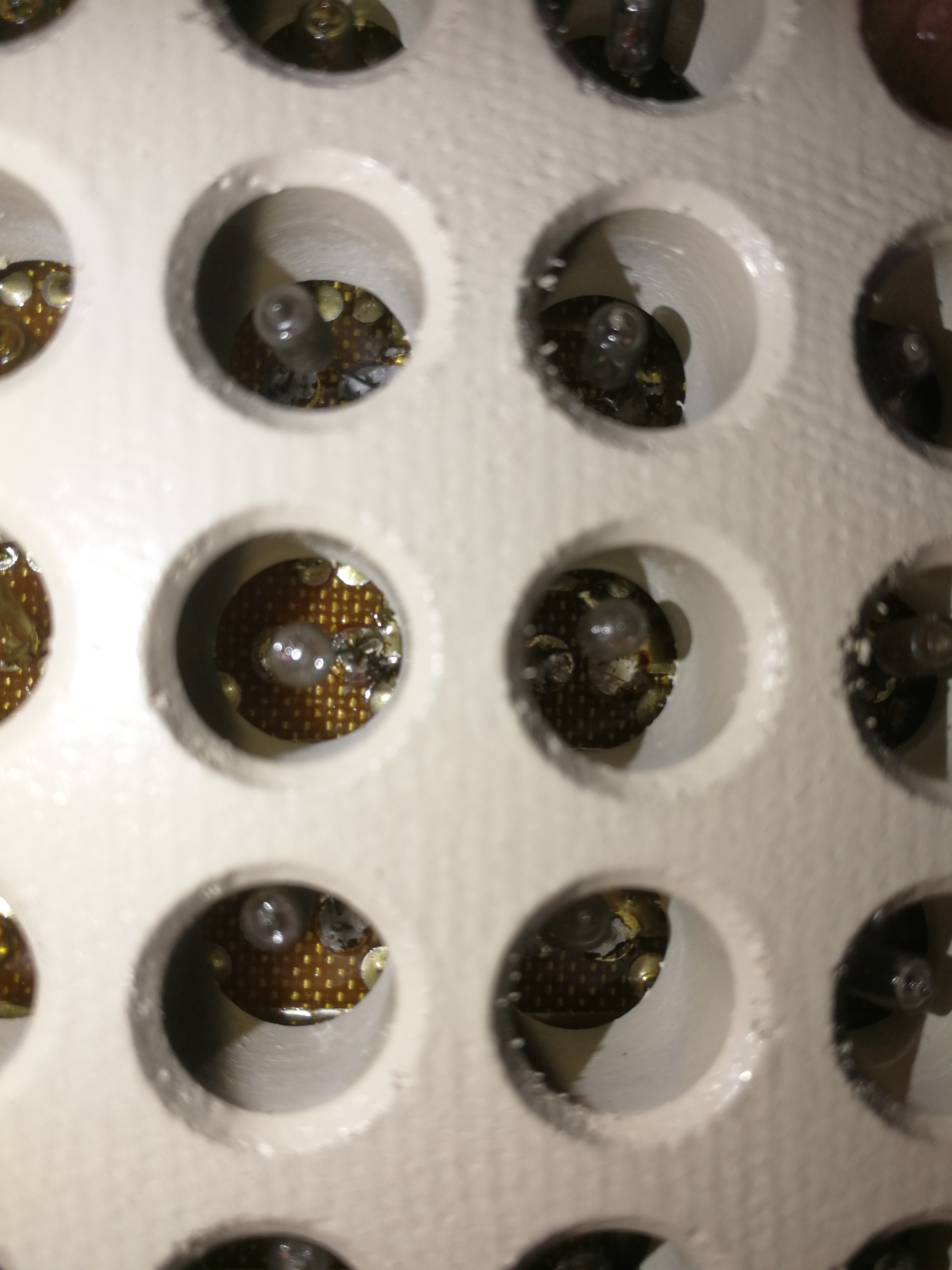
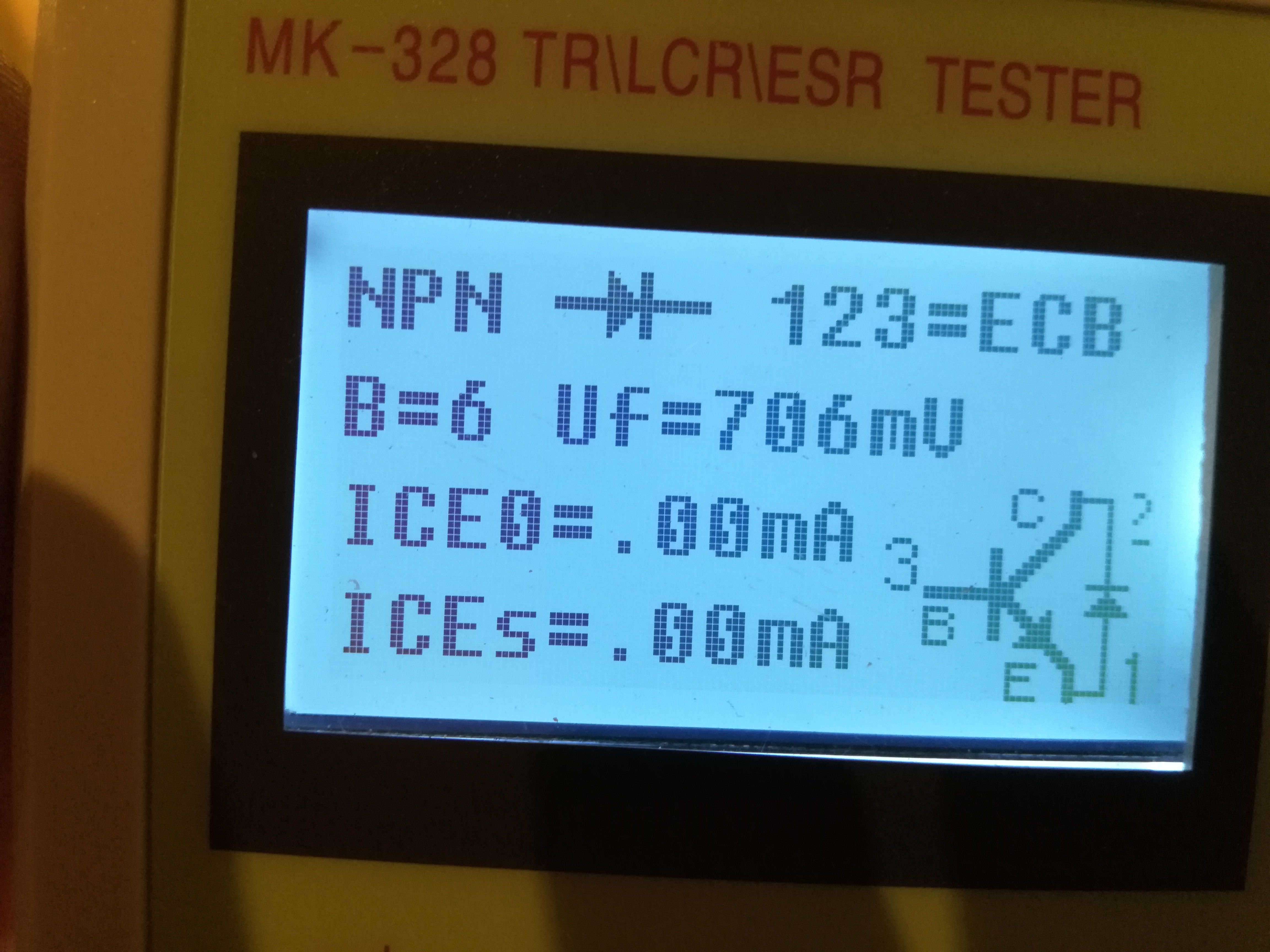
Can anyone help me identify what these transistors might be:
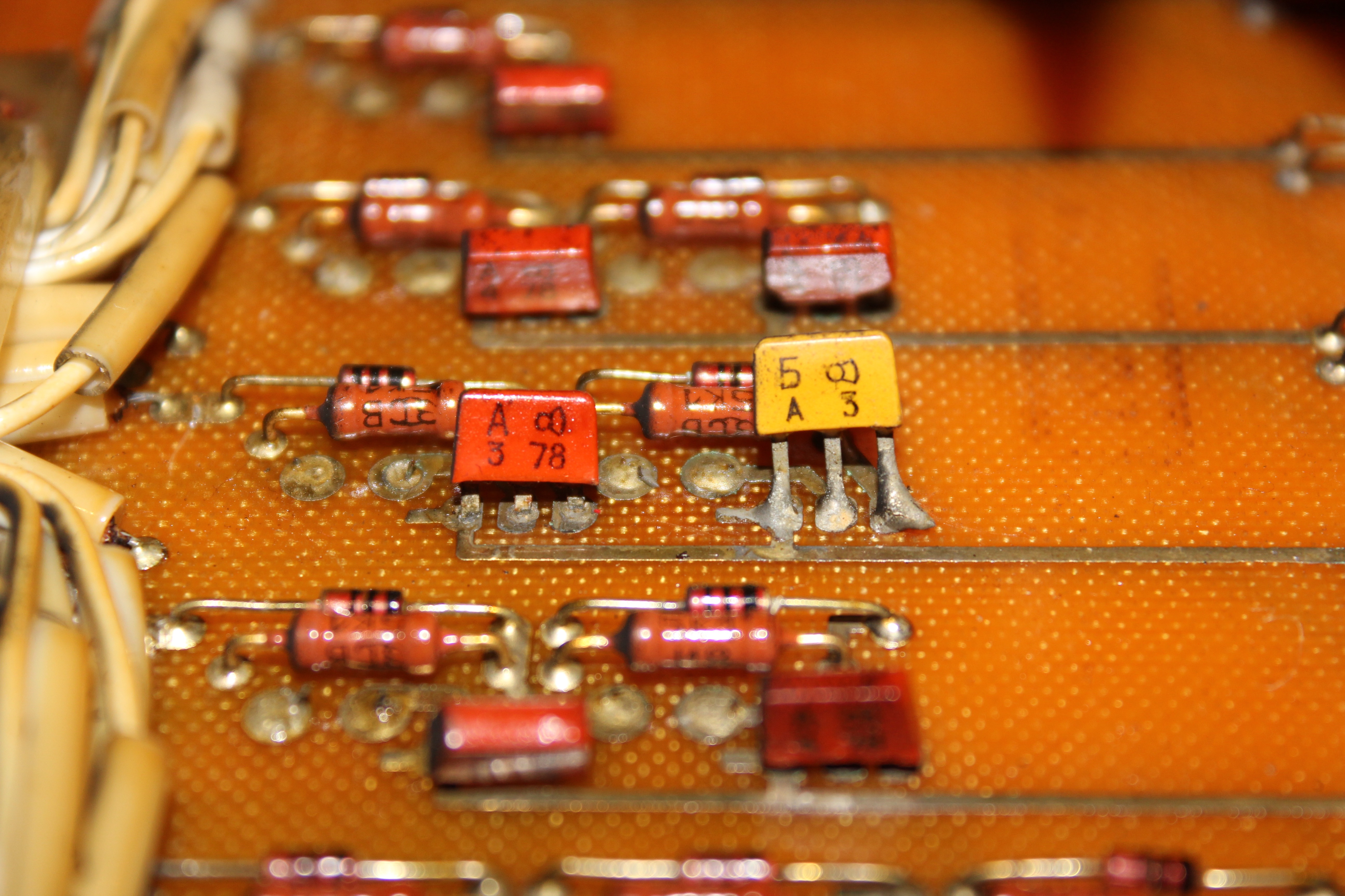
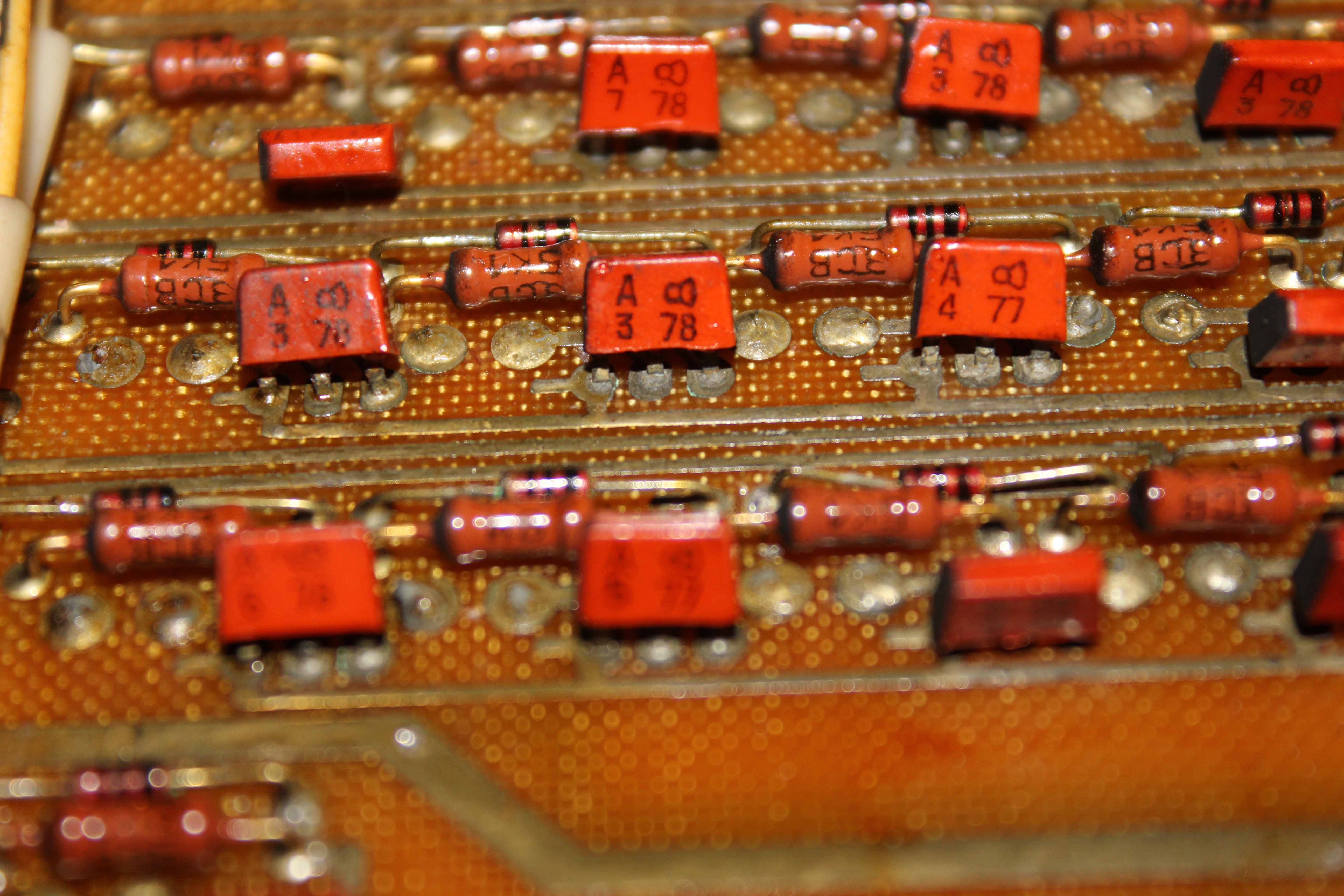
More later!
It all takes time.